What are the Component Parts of a Well Foundation
A section through a well foundation is shown in figure 1. The various component parts of a Well Foundation are briefly described in the following.
Well Cap –
The well cap is a RCC slab of sufficient strength to transmit the forces from pier to the body of well. It is generally kept at low water level. The dimension of the well cap should be sufficient to accommodate the pier. The recommended minimum thickness is 0.75 m.
Steining –
It is the wall of well & is built over a wedge shaped portion called well curb. The steining is designed such that it can be sunk under it own weight. The thickness should be sufficient so as to overcome skin friction developed during sinking by its own weight. The minimum reinforcement in the well staining should be 5 to 6 kg/m3 of which 75 % is to be provided as vertical and 25 % as lateral ties or hoop rings. The minimum thickness is 0.45 m or 1/ 8 of the external dia. of well for brick masonry and 1/10 for wells with cement concrete. The thickness is increased by 12 cm per each 3 m depth after sinking the 3 m of steining for brick well and 15 cm for each 6 m depth after sinking the first 6 m of cement concrete well. The thickness can be computed as:
![t = \dfrac{D}{2}[1-\sqrt{1-\dfrac{4q_s}{\rho}}]](https://s0.wp.com/latex.php?latex=t+%3D+%5Cdfrac%7BD%7D%7B2%7D%5B1-%5Csqrt%7B1-%5Cdfrac%7B4q_s%7D%7B%5Crho%7D%7D%5D&bg=ffffff&fg=000&s=0&c=20201002)

Where D is the diameter of well, qs is the unit skin friction, 
|
D(m) |
3 |
5 |
7 |
|
t(m) |
0.75 |
1.20 |
2.00 |
The thickness of the steining is also given by,
![t = k[\dfrac{B}{8}\times \dfrac{H}{100}]](https://s0.wp.com/latex.php?latex=t+%3D+k%5B%5Cdfrac%7BB%7D%7B8%7D%5Ctimes+%5Cdfrac%7BH%7D%7B100%7D%5D&bg=ffffff&fg=000&s=0&c=20201002)
Where k = 1 for sand, 1.1 for soft clay and 1.25 for hard clay and boulder.
The skin friction, which is developed during sinking a well/caisson, is difficult to estimate by soil tests. The load at which a well gets stucked during sinking is taken as the skin friction. Experience has suggested that the skin friction is fairly constant below a depth of 7.5 m. The following table gives the values that have been obtained for wells ranging in depth from 7.5 m to 37.5 m.
|
Soil Type |
Skin Friction (kN/m2) |
|
Silt and Soft Clay |
7.3 – 29.3 |
|
Very Stiff Clay |
49 – 195 |
|
Loose Sand |
122 – 242 |
|
Dense Sand |
342 – 648 |
|
Dense Gravel |
490 – 940 |
Well Curb –
The well curb supports the steining. The curb should be slightly projected from the steining to reduce the skin friction during sinking of well. It is made of RCC with steel cutting edge. The minimum reinforcement to be provided is 72 kg per cubic meter. The inner portion of the steining should have a slope of 2:1 (V:H).
Cutting Edge –
The cutting edge is either projected below the curb as a sharp edge or can also have flat bottom. The projected edge is likely to be damaged in strata of gravels and boulders. In such soils the flat bottom cutting edge is provided.
Bottom Plug –
The bottom plug is made bowled shape in order to have an arch action. The bottom plug transmits load to soil below. When sunk to its final depth bottom part is concreted to seal the bottom completely. The thickness varies from ½ to full inside diameter of the well so as to be able to resist uplift forces. The concreting should be done in one continuous operation. When wells contain more than one dredge hole all should be plugged to the same height. If the well is to rest on rock, it should be anchored properly by taking it 25 cm to 30 cm deep into rock The bottom plug should be of rich concrete (1:2:4) with extra 10 % of cement. The thickness of the bottom plug is given by:

and 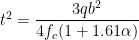
Where q is the bearing pressure at base of well, R is the radius of the arc b is the width of well, fc is the flexural strength of concrete seal and, ![]alpha = \dfrac{Width}{Length}](https://s0.wp.com/latex.php?latex=%5Dalpha+%3D+%5Cdfrac%7BWidth%7D%7BLength%7D&bg=ffffff&fg=000&s=0&c=20201002)
Sand Filling –
After concreting the bottom plug the sand is filled above the bottom plug and below top plug. Sand filling provide stability of well, reduce tensile stress produced by bending moment and distributes the load of super structure on to the bottom plug. Sand filling relieves load to steining to some extent.
Top Plug –
This is a plug at the top of the well below the well cap. This helps transferring the load through the granular material into the staining.
You may also like Sinking of well Foundation.
Check out other top popular Articles :
Clock Signal Generator Circuit